Every Material is Different
This is a series of files you can download and use to test and log materials settings for your CO2 laser system. There is a test file to download for both Vector and Raster (Current test coming soon).
Make sure to use the provided test log to keep track of the best results. All materials are different, there are no EXACT settings to do anything using a laser as laser output varies with age, and even materials act differently in different atmospheric conditions.


Instructions
Before you begin, just know that this process will take a little extra time and will use extra materials, but the final results will save you that time in future projects.
What you'll need
⊳ Extra Materials (Use scraps if possible)
⊳ Test File (Download linked above)
⊳ Material Test Log (Download linked above)
⊳ Laser Cutter and Engraver
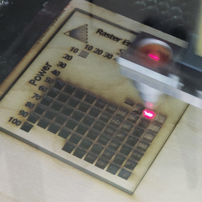
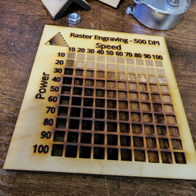
Raster Test
Step One: Start Laser and load RetinaEngrave v3.0 on your computer.
Step Two: Load the .re3 raster test file by selecting "File" then "Load Project from File..."
Step Three: Place your material in the laser and use the run perimeter function in RE3 to make sure it is properly positioned (or you can use the camera if you have one).
Step Four: Close the lid, make sure the water and air assist are running, and then start the job. The settings are already pre-programmed into the file, so it will utilize each variance as it hops from square to square. (Make sure you disable vector sorting in the settings, that way it will run as it is organized in the file).
Step Five: Once the laser has completed the test, examine the results to pick the ideal settings for your material. Make sure you log this information using the Material Test Log which is available to download above.
Vector Test
Step One: Start Laser and load RetinaEngrave v3.0 on your computer.
Step Two: Load the .re3 vector test file by selecting "File" then "Load Project From File..."
Step Three: Place your material in the laser and use the run perimeter function in RE3 to make sure it is properly positioned (or you can use the camera if you have one).
Step Four: Close the lid, make sure the water and air assist are running, and then start the job. The settings are already pre-programmed into the file, so it will utilize each variance as it hops from square to square. (Make sure you disable vector sorting in the settings, that way it will run as it is organized in the file).
Step Five: Once the laser has completed the test, examine the results to pick the ideal settings to use for vector cutting your material. Look at the front side of your results and find the one that completely cut through the material with minimal charring on the edge. Then flip the material over and look at the back side to make sure you find the one that had the lease amount of flash back onto the material. If multiple options are close and you are having a hard time choosing, pick the combination that has the highest speed and lowest power.
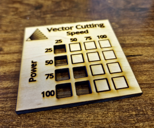
Front: Find the cut with the least visible charred edge
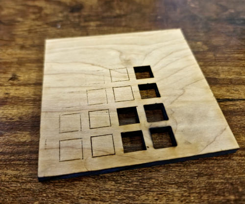
Back: Find the cut that has the least amount of flashback onto the surface
Make sure you log this information using the Material Test Log which is available to download above. To reduce the amount of charring on the cut, you can adjust the current settings (see current test below).
Current Test
(COMING SOON)