
Let's get rid of that water bucket...
When your Coolbox arrives, follow these simple instructions to replace your current water pump/bucket and air assist with your Coolbox.
UNBOXING
First, we will unbox the Coolbox and the assembly parts. Carefully remove the items from the box as directed below:
- Remove the Top Foam. Beneath the top foam, you will see the coolbox and all needed accessories.
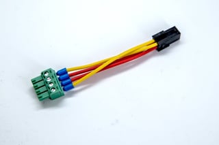
- Remove Right Packaging Box. Remove the larger box to the right and check that all the following parts are included: 2-Pin Cable (1), 4-Pin Cable (1) and AC Power Cable (1).
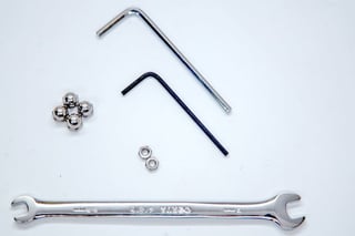
- Remove Left Packaging Box. Remove the smaller box to the left and check that all the following parts are included: Cooling Fan (1), 4-Pin Molex to 4-Pin Terminal Connector (1) & and a small plastic bag containing: 2mm Hex key (1), 2.5mm Hex Key (1), 5.5/7mm Wrench (1), two M3 Nuts (2) and four Acorn Nuts (4).
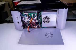
- Remove Coolbox. Start by removing the three pieces of side foam, securing the coolbox. Then, gently lift the coolbox from the box. You can lift and remove the adapter plate and the foam sheet at the same time as the coolbox.
- Remove Exhaust Fan Cowling. Remove the exhaust fan cowling and its support foam.
- Remove Muse Side Panel. Remove foam covering the side panel. Remove the new Muse side panel from the box. Your coolbox is unboxed.
PARTS CHECKLIST
You Should have the following parts for assembly once you have completed unboxing your Coolbox:
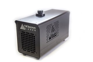
Coolbox Unit (1)
Exhaust Fan Cowling (1)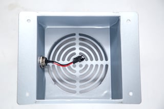
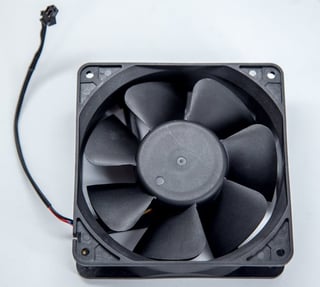
Exhaust Fan (1)
Adapter Plate (1)
Muse Side Panel (1)
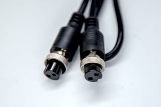
2-Pin Cable (1)
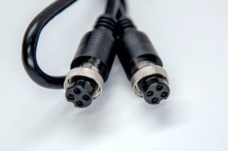
4-Pin Cable (1)
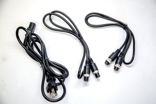
AC Power Cable (1)
4-Pin Molex to 4-Pin Terminal Connector (1)
2mm Hex Key (1)
2.5mm Hex Key (1)
5.5/7mm Wrench (1)
M3 Nuts (2)
M4 Acorn Nuts (4)
ASSEMBLY
Follow these instructions to replace the current water pump/bucket cooling system and the old air assist with your new Coolbox:
- Safety First. Before starting this procedure, turn off your muse and unplug it from all power sources. We recommend to wait at least 20 minutes to ensure no residual electricity remains.
- Remove Existing Exhaust Plate.
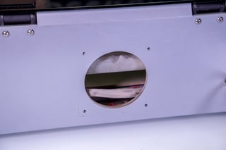
Using the provided 2.5mm hex key, remove the four (4) screws from the existing exhaust plate and set them aside in a secure location. Then remove the existing exhaust plate. You will no longer need the old exhaust plate, however, hold on to two (2) of the screws to secure the new adapter plate, in the next step. - Attach Adapter Plate.
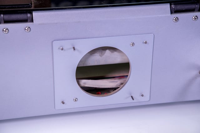
Using the 2.5mm hex key and the two (2) screws saved from removing the exhaust plate (see step 2), attach the adapter plate on the back of your Muse, where the old exhaust plate was. - Attach Exhaust Fan.
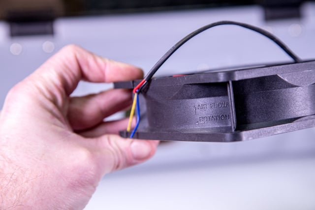
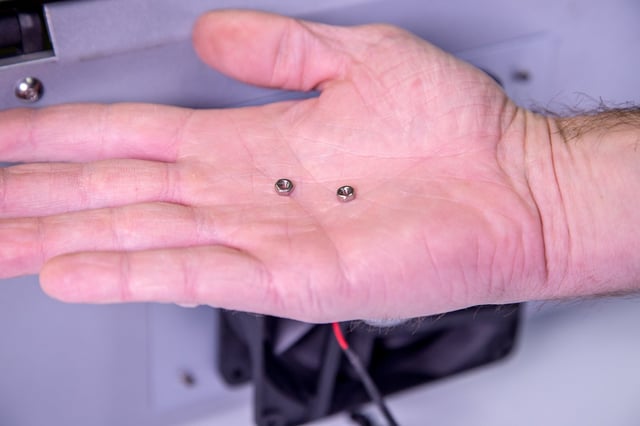
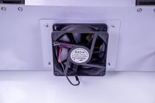
Using the 5.5/7mm wrench, attach the exhaust fan to the adaptor plate with the two (2) M3 Nuts. Note that the arrow on the fan needs to be pointing out the case.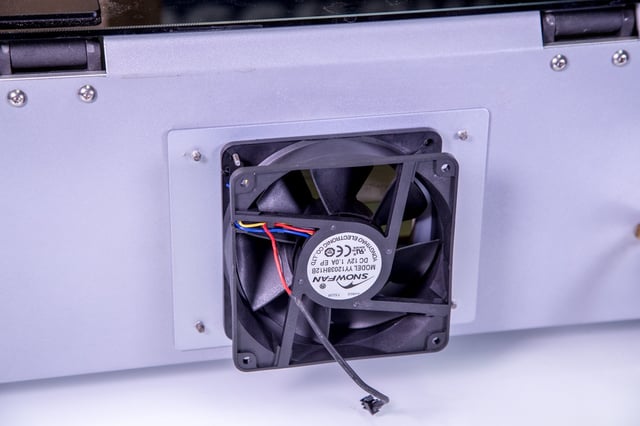
- Connect Exhaust Fan to Cowling.
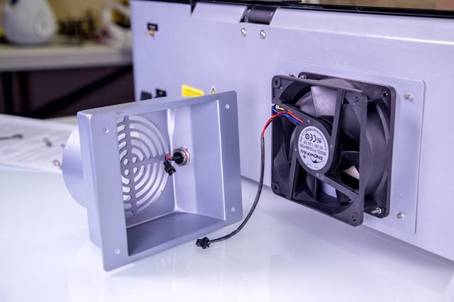
Carefully connect exhaust fan connector to exhaust fan cowling connector. Do not force the connection. The connectors only fit one way and should gently slide together and secure.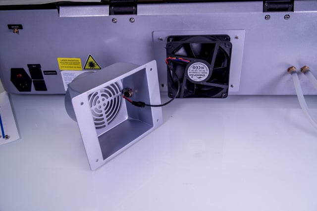
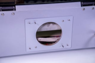
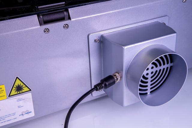
- Attach Fan Cowling to Adapter Plate.
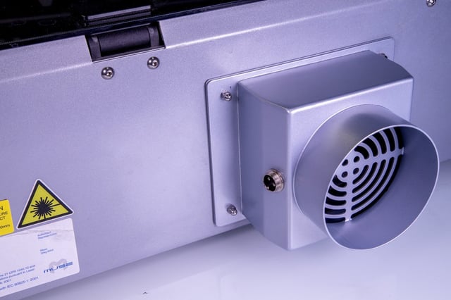
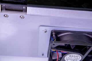
Carefully slide the fan cowling onto the adapter plate by aligning it straight and then pushing forward. Hold the cowling steady and secure with the four (4) acorn nuts. Tighten until secure using your fingers or the provided 5.5/7mm wrench. IMPORTANT: Once cowling is attached, make sure the wires are not interfering with the fan. Inspect visually and then spin the fan by hand from the inside of the Muse to ensure it is unobstructed.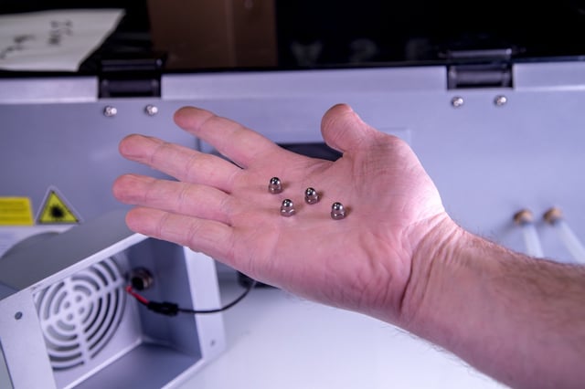
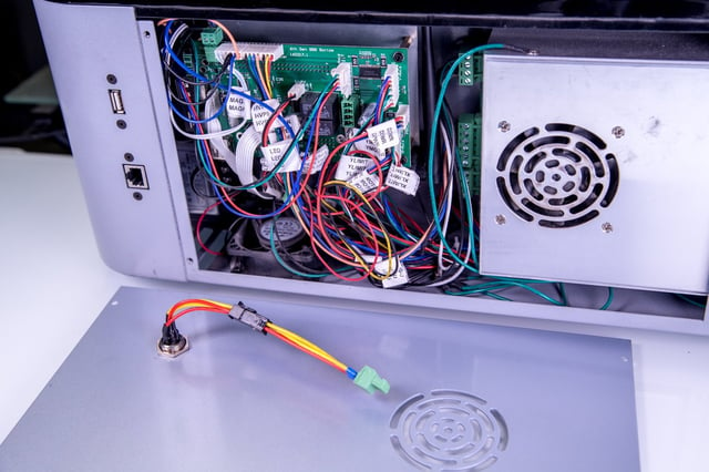
- Remove Muse Side Panel.
On the right side of the machine is a side access panel. Note the positioning of the panel, as we will replace this panel with a new panel in exactly the same position. Using the provided 2mm hex key remove the four (4) M3 screws securing the existing side panel. Place these in a safe place to use again.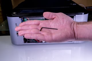
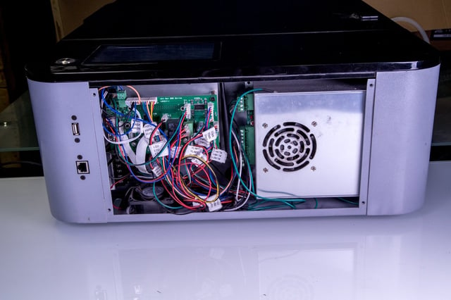
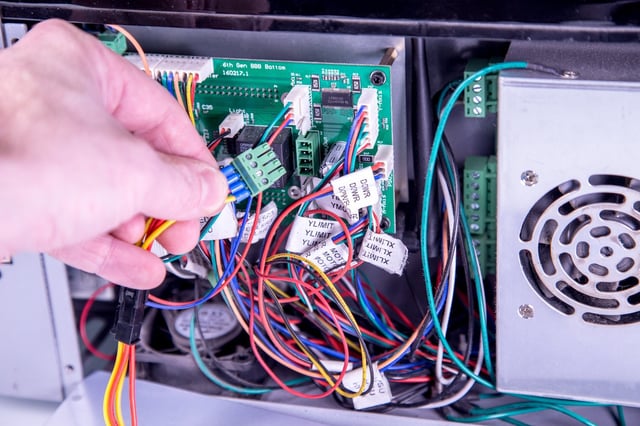
- Disconnect Green Connector from Relay.
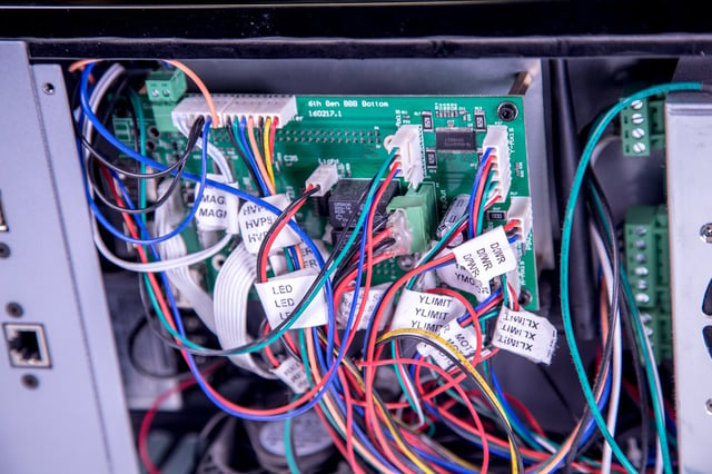
With the side panel removed, disconnect green 4-pin terminal from control card. Note the location. We will plug our new side panel 4-Pin terminal here. You will no longer need the old side panel.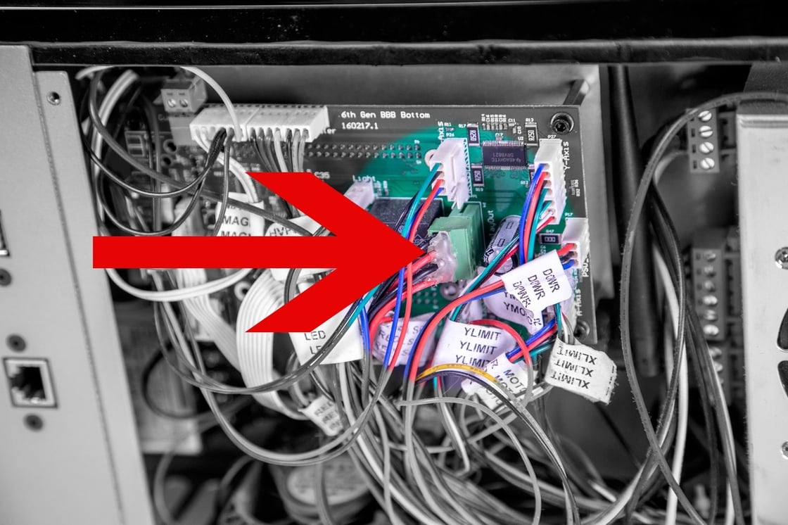
- Connect 4-Pin Molex to New Side Panel.
Gently slide the 4-Pin Molex end of the 4-Pin Molex to 4-Pin Terminal Connector to its counterpart on the new side panel. Do not force. The connectors only attach one way, with the clip ends joining together and clicking when secure.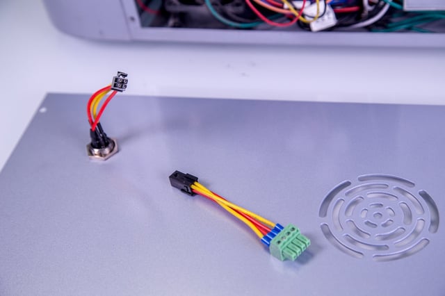
- Connect New 4-Pin Terminal to Control Card.
While holding the new side panel close the control card, carefully connect the green 4-pin terminal into the same green slot the prior 4-pin terminal occupied. Be careful not to pull on the side panel, which may cause the connections to disengage.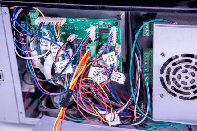
- Attach New Side Panel.

Using the four (4) M3 screws that previously held the old side panel, secure the new side panel using the provided 2mm hex key. Note the positioning. The cooling slots should be directly over the power source cooling fan.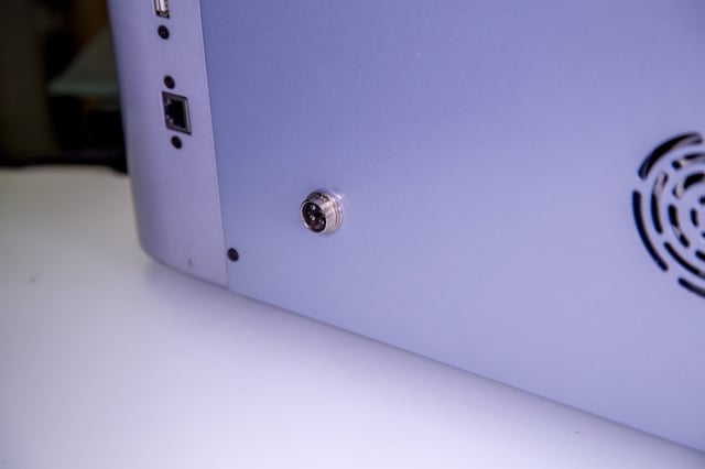
- Connect Air Assist Hose to Coolbox.
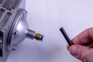
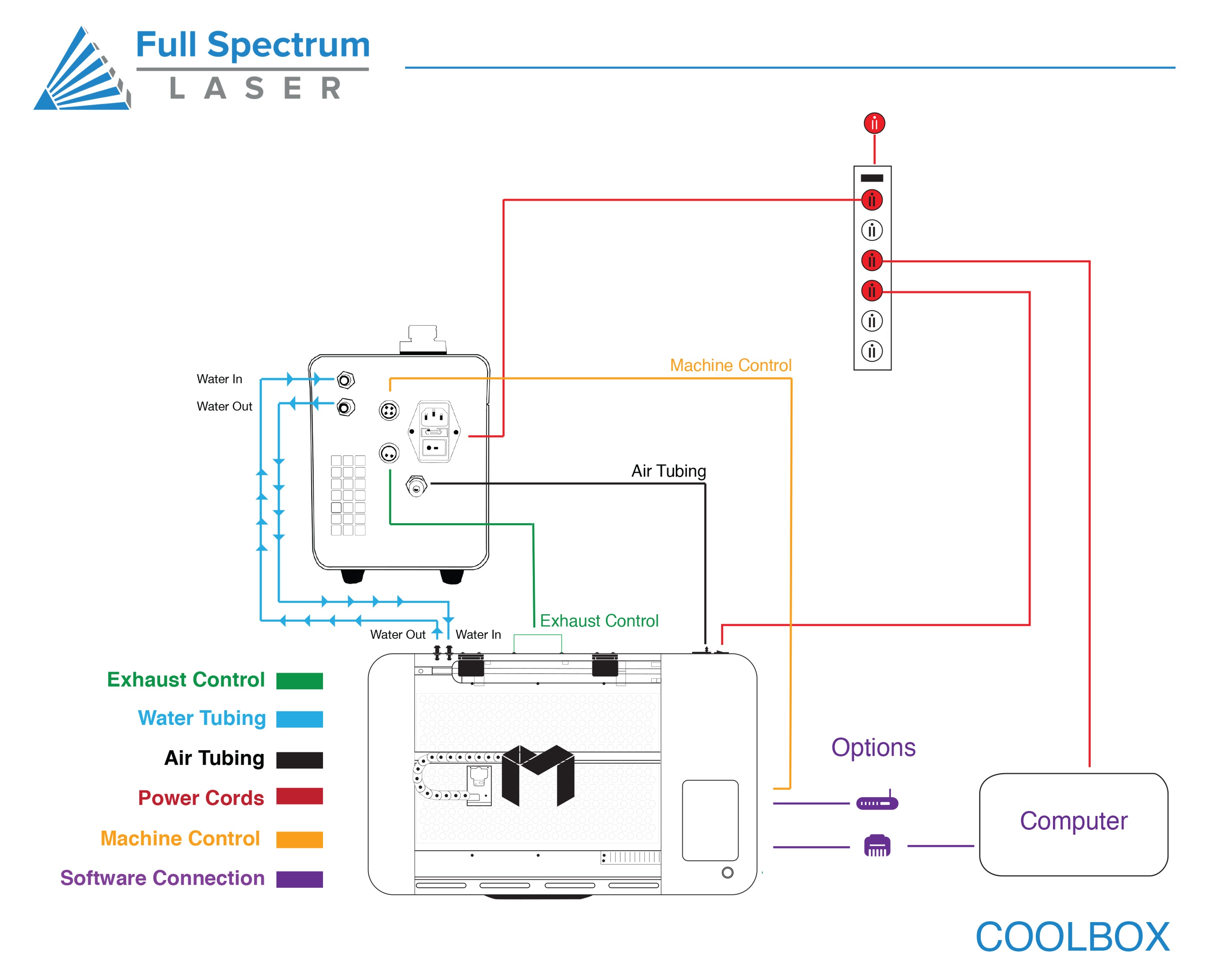
Disconnect the air assist hose from your existing air pump. Do not disconnect the other end of the air assist hole from your Muse. Next, attach the air assist hose to the “Air Out” port on your coolbox.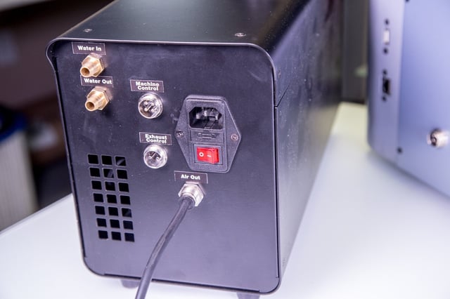
- Connect Exhaust Fan to Coolbox.
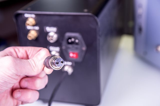
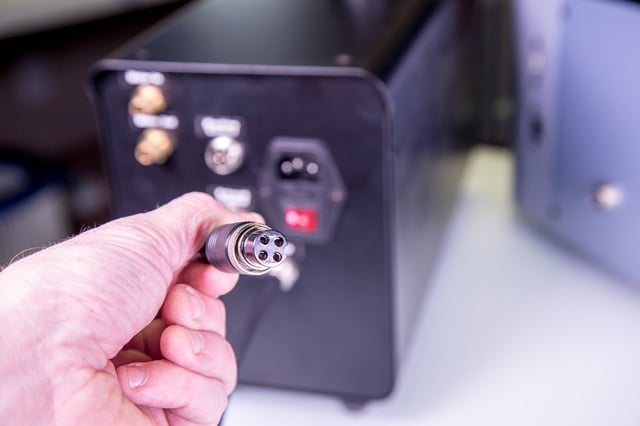
Using the provided 2-Pin Cable attach one end to the slot on the fan cowling and the other to the back of the coolbox, in the slot labeled “Exhaust Control”. Once each is snug in the slot, gently turn the metal rings on each end of the connector and tighten.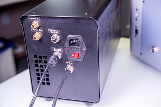
- Connect Side Panel to Coolbox.
Using the provided 4-Pin Cable, attach one end to the slot on the new side panel and the other to the back of the coolbox, in the slot labeled “Machine Control”. Once each is snug in the slot, gently turn the metal rings on each end of the connector and tighten.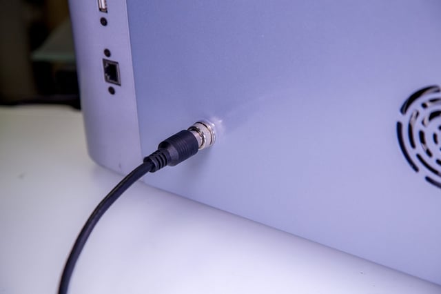
- Connect Water Tubing to Coolbox.
WARNING. The water tubes may contain water if you have used the machine. Have a towel ready to catch any excess water that may pour out of your tubing and avoid spilling on electronic components or sources of electricity.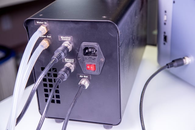
Detach the “Water In” water tube from the existing water pump and securely attach it to the “Water Out” slot on the back of the coolbox. Next, take the unconnected “Water Out” tube (the end that went to your water bucket) and securely attach it to the “Water In” slot on the back of your Muse. This will create the proper circulation of water through the laser tube and back to the coolbox.
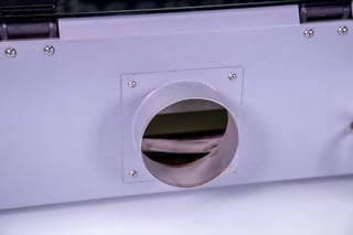
- Connect Ducting to Exhaust Port. Place your 4” ducting over the Exhaust Port located at the back of the machine and hold. Secure with 4” ducting clamp or industrial ducting tape.
- Connect Power Cord.
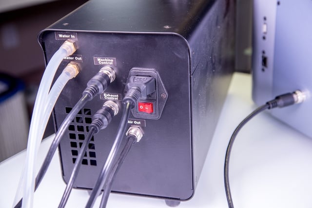
Insert the Non-Outlet end of the power cord to the back of the coolbox, in the AC power slot just above the power switch. Next, plug the other end into an appropriate outlet. DO NOT plug the Coolbox into the slots in the back of your Muse.
USING YOUR COOLBOX
Remember to always have your coolbox running when you are using the laser.
- Add Distilled Water. Unscrew water cap. Fill tank with distilled water (approx. 1250 ml). Put cap back on and tighten.
- Power On Coolbox. Flip the red power switch to the “On” position. Remember to always run your coolbox when the laser is operating.